
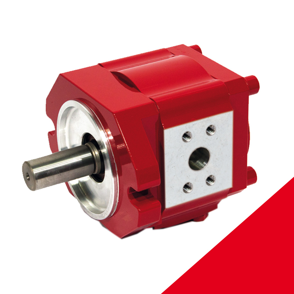
The internal gear pump’s volume formation takes place between the tooth chambers and housing walls or sickle.
V8 = m . z . b . h .\
V8 = geometrical stroke displacement
m = module
z = number of teeth
b = tooth width
h = tooth height
Internal gear pump function
By rotating the inner gearwheel in the direction of the arrow, the external gear wheel is moved in the same direction
The rotational movement means that the gear wheels in the suction area move apart so that the two spaces left free are filled with fluid from the suction chamber.
The hydraulic pump is available in different pressure stages and constructions.
Different manufacturers produce higher pressure compensation, resulting in increased efficiency.
The pumps are available as multiple pumps and pump combinations.
There are also special designs available for special operating methods and application locations such as mobile and offshore use.
Repair kits are sometimes provided. However, the question as to whether repair in an individual pump is economically viable is a tricky business that requires expert opinion.
Internal gear pump applications
Internal gear pump applications include the following:
- Industrial applications
- Forestry and agricultural machines
- Fan motors
- Simple winch drives
- Mobile applications
- Variable speed drive, Kinesys
The design can also be used as a hydraulic motor.
Internal gear pump technical data and characteristics
Internal gear pump technical data and characteristics include the following:
- Constant stroke volume per stage from 3.5 up to maximum approximately 25cm3/rev
- Maximum pressure up to approximately 350 bar *speeds from 200rpm up to 3600rpm
- Low noise and low degree of unevenness *versions up to three stages
- Various pressure fluids are possible
For further information call HYDAC Australia on 1300 449 322 or email info@hydac.com.au.
Contact us for more information


